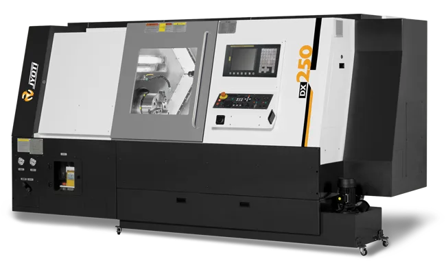
DX
Key Features
- Rigid bed and single piece 45°slant structure.
- Powerful high torque spindle with rigid headstock.
- Wide liner motion roller type guide ways.
- High speed – high precise bi-directional servo turret.
- Live tool turret option available for milling operations.
- Ergonomically design concept.
- Efficient chip removal without disturbing machining.
- Tail stock with hydraulic quill.
- Hydraulic chucking.
- Auto and manual coolant system.
- Electrical with quality devices & panel with A.C.
- Centralized & programmable lubrication.
- Monoblock rigid Structure
- 3-point Leveling
- Bi-directional servo turret
- TPM Friendliness
| DX 250 - 500 | DX 250 - 700 | DX 250 - 1000 | DX 350 - 700 A | DX 350 - 700 B | DX 350 - 1000 A | DX 350 - 1000 B | DX 350 - 1500 A | DX 350 - 1500 B | DX 350 - 2000 A | DX 350 - 2000 B | ||
| Capacity | ||||||||||||
| Swing Over Bed | mm | 500 | 600 | 600 | 740 | 740 | 740 | 740 | 740 | 740 | 680 | 680 |
| Std. Turning Dia. | mm | 300 | 300 | 300 | 415 | 415 | 415 | 415 | 415 | 415 | 415 | 415 |
| Max. Turning Dia.* | mm | 490 | 480 | 480 | 600 | 600 | 600 | 600 | 600 | 600 | 600 | 600 |
| Max. Turning Length* | mm | 500 | 700 | 1000 | 700 | 700 | 1000 | 1000 | 1500 | 1500 | 2000 | 2000 |
| Slides | ||||||||||||
| X-Axis Travel (Cross) | mm | 250 | 250 | 250 | 310 | 310 | 310 | 310 | 310 | 310 | 310 | 310 |
| Z-Axis Travel (Longitudinal) | mm | 500 | 700 | 1000 | 700 | 700 | 1000 | 1000 | 1700 | 1700 | 2000 | 2000 |
| Rapid Feed (X & Z axis) | m/min | 24 | 24 | 24 | 24 | 24 | 24 | 24 | 24 | 24 | 24 | 24 |
| Main Spindle | ||||||||||||
| Spindle Motor Power - Siemens | kW | 14.4/11 | 15.6/12 | 15.6/12 | 15.6/12 | 27.8/18.5 | 15.6/12 | 27.8/18.5 | 15.6/12 | 27.8/18.5 | 15.6/12 | 27.8/18.5 |
| Spindle Motor Power - Fanuc | kW | 15/11 | 15/11 | 15/11 | 15/11 | 18.5/15 | 15/11 | 18.5/15 | 18.5/15 | 22/18.5 | 18.5/15 | 22/18.5 |
| Spindle Speed Range | rpm | 50-3500 | 50-2500 | 50-2500 | 50-2500 | 50-1500 | 50-2500 | 50-1500 | 50-2500 | 50-1500 | 50-2500 | 50-1500 |
| Spindle Bore | mm | 90 | 80 | 80 | 80 | 110 | 80 | 110 | 80 | 110 | 80 | 110 |
| Spindle Nose | A2-8 | A2-8 | A2-8 | A2-8 | A2-11 | A2-8 | A2-11 | A2-8 | A2-11 | A2-8 | A2-11 | |
| Max. Bar Capacity | mm | 75 | 65 | 65 | 65 | 90 | 65 | 90 | 65 | 90 | 65 | 90 |
| Turret | ||||||||||||
| No. of Tool Station | 8 | 8 | 8 | 8 | 8 | 8 | 8 | 8 | 12 | 8 | 12 | |
| Max. Boring Bar Dia. | mm | 40 | 40 | 40 | 40 | 50 | 40 | 50 | 50 | 50 | 50 | 50 |
| Tool Size (Cross Sectional) | mm | 25 X 25 | 25 X 25 | 25 X 25 | 25 X 25 | 32 X 32 | 25 X 25 | 32 X 32 | 32 X 32 | 32 X 32 | 32 X 32 | 32 X 32 |
| Tail Stock | ||||||||||||
| Quill Dia. | mm | 85 | 100 | 100 | 100 | 100 | 100 | 100 | 130 | 130 | 130 | 130 |
| Quill Stroke | mm | 120 | 120 | 120 | 120 | 120 | 120 | 120 | 150 | 150 | 150 | 150 |
| Thrust (Adjustable) | kgf (Max.) | 500 | 500 | 500 | 500 | 500 | 500 | 500 | 1000 | 1000 | 1000 | 1000 |
| Accuracy (As per VDI/DGQ 3441) | ||||||||||||
| Positioning Uncertainty (P) | mm | 0.007 | 0.01 | 0.01 | 0.01 | 0.01 | 0.01 | 0.01 | 0.015 | 0.015 | 0.015 | 0.015 |
| Repeatability (Ps medium) | mm | 0.005 | 0.005 | 0.005 | 0.005 | 0.005 | 0.005 | 0.005 | 0.007 | 0.007 | 0.007 | 0.007 |
| Other Data | ||||||||||||
| Machine Weight # (Approx.) | kg | 4000 | 5750 | 6000 | 6500 | 6500 | 6750 | 6750 | 10000 | 10000 | 10200 | 10200 |
| Machine Dimension # (Approx.) | ||||||||||||
| Length | mm | 2400 | 3080 | 3500 | 3060 | 3060 | 3560 | 3560 | 5050 | 5050 | 5550 | 5550 |
| Width | mm | 1600 | 1890 | 1890 | 1950 | 1950 | 1950 | 1950 | 2820 | 2820 | 2820 | 2820 |
| Height | mm | 1660 | 1900 | 1900 | 2020 | 2020 | 2020 | 2020 | 2370 | 2370 | 2370 | 2370 |
* Depend upon clamping arrangement, Tooling & Job
# Refer machine detailed layout
